Cables
-
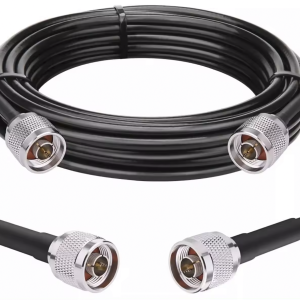
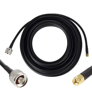
LL400 Coaxial Cable, N Male to N Male
$74.00 – $194.00 -
LL400 Coaxial Cable N Male to SMA Male
$74.00 – $194.00 -
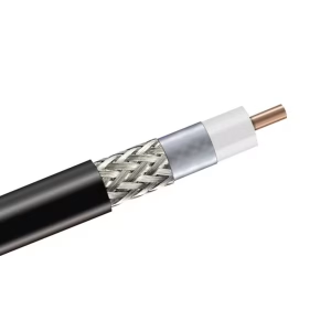
LL400 Coax Cable – Per Meter
$0.00 -
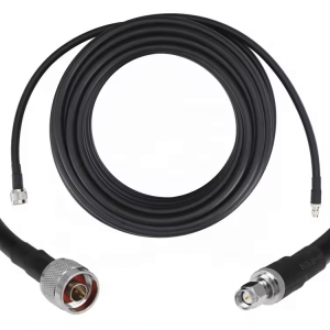
LL240 Coax Cable N Male – SMA Male
$35.00 – $60.00 -
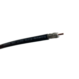
Hills Antenna 50 Ohm LL240 Coaxial Cable – Per Meter
$0.00 -
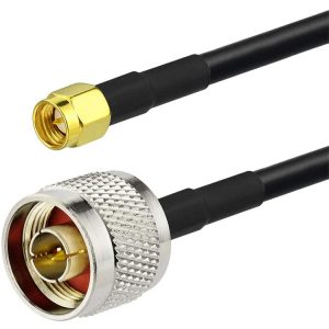
LL195 Coax Cable N Male to SMA Male
$25.00 – $34.00 -
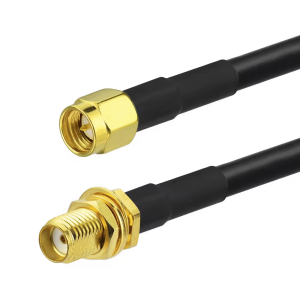
LL195 SMA Male to SMA Female
$29.00 – $37.00 -

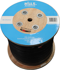
Hills LL400 Coax Cable -305m Roll
$858.00 -
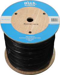
Hills LL400 Coax Cable – 100m Roll
$374.00 -
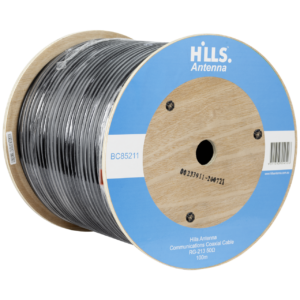
Hills LL240 Coax Cable – 305m
$599.00 -
Hills Antenna RG213 Coaxial Cable -100M Roll
$440.00